mhm, ok, i read "this" I think,U need only connect GND with GND and Signal with one of the End Stop Pins. But u need this jumper. Becouse END Stop Pins on GRBL Shield dont have GND.
Sorry I didn't find time to test whether the "Opto endstops" works with your example of connections, i'll keep you informed of that is done.
I translated the comments of your image to better understand them and do you think this type of module ( http://www.thingiverse.com/thing:22202 ) may be suitable to connect two fans on my "CNC Shield"?
Oh yes, I forgot, my "CNC Shield" is version 3.0 so i can't choose the type of endstop with jumper (normally open or normally closed) !!!
Zitieren:I translated the comments of your image to better understand them and do you think this type of module ( http://www.thingiverse.com/thing:22202 ) may be suitable to connect two fans on my "CNC Shield"?
yes, u need an adapter, or u need soldering for two Fans on one Mosfetdriver.
in Germany from myhobby-CNC you can only get the GRBL-Shield Revision 1.00 of board. Other versions are from other companies.
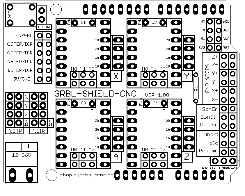
The shield only wires the Arduino pins to the right position. As you can see, there are no active components which do anything with the signals.
Now to your endstops and fan. The connectors for the endstops are on the far right side of the board. There are two pins for one end stop in a horizontal row. The right one goes to the middle pin of the tree pin header at the right bottom. At this header you can choose if all right end stops pins should have GND or VCC (+5V) level! This is the counterpart of the end stop signals of the arduino. The left pin of the end stops goes direct to the corresponding Arduino pin, as defined in the GRBL-Pinoute definition. So you can switch your signal against GND or VCC, as you need it! Moreover you can use the internal pull up resistor of your ATmega!
The same is with the fan. You can use the pin "CoolEn" to start a cooling eqipment. To switch a motor or any other device, you can use optocoupler, MOSFETs, SSR (solid state Relais) ore any other switcher.
Thanks Ronald, but i don't have this/your shield !!! I have the version 3.00 of "Protoneer" Shield. In your version 1.00 and in the version 3.02 of "Protoneer" Shield, the jumper at the bottom right was added and other little improvements.

 Anmelden